Introduction
A charge controller is an essential part of nearly all power
systems that charge batteries, whether the power source is PV, wind, hydro,
fuel, or utility grid. Its purpose is to keep your batteries properly fed and
safe for the long term
The
basic functions of a controller are quite simple. Charge controllers block
reverse current and prevent battery overcharge. Some controllers also prevent
battery over discharge, protect from electrical overload, and/or display
battery status and the flow of power
Hardware
Interface Of Charge Controller
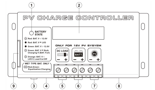
The following diagram shows the hardware interface of the PV Charge
Controller
 |
Front view of PV Charge Controller
|
Where
- 1 Battery LED Indicator
- 2 LCD Display
- 3 Reset button
- 4 Temperature Sensor (Optional )
- 5 .12V DC Load terminal with Low Voltage Disconnect/NIGHT-LIGHT mode
- 6 12V Battery connection terminal
- 7 PV Panel connection terminal
- 8 Remote Signal Terminal (Optional )
- 9 Side Door (open to access switches for setting)
Connection
of Charge Controller
The PV Charge Controller
should be connected as follow
 |
Connection of PV Charge Controller
|
This diagram illustrates the
connectivity of a typical solar power kit, including a solar panel, a solar
charge controller, a battery and the load (e.g. a light bulb). The solar panel
connects to the controller through positive and negative leads, only creating a
charging function when the controller is connected to a battery. The load is
then responsible for the discharging function from the controller (if it is connectedto
the controller)
In some rare cases, a solar panel can be connected directly to a battery,
without a controller. This can be achieved if the nominal voltage of the panel
is lower than 17-18V, and if the solar panel is a lot smaller than the charging
battery e.g. a 10Wpanel charging a 100Ah battery


No comments:
Post a Comment